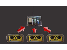
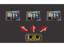
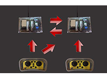
All transmitters of from the JMei radio remote control range can be configured in terms of addresses, frequencies and stand-by using their switches.
These memory data can be easily modified by maintenance personnel in the event of switching or replacement of a transmitter (in case of breakdown or breakage).
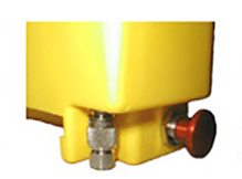
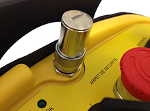
In order to simplify these operations and to minimise service calls, the essential operational parameters (address, frequency, stand-by, etc.) may be enclosed within a "hardware identification key", a real radio control memory key.
This external memory, which is removable, can be easily changed by the operator and is unique for a given piece of machinery.
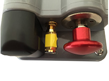
In the event of failure of a transmitter, the operator can easily remove (unscrew without special tools), the identification key and put it back on the emergency transmitter. All of the settings for the piece of machinery concerned will be transferred into the reserve, configured and ready-to-use. In addition, this key is fitted on each type of JMei transmitter at a protected location (against the risks of breakages) but one that is easy to access.
The JMei/TCA27 system enables safety to be increased considerably when controlling dangerous machinery.
A typical accident which may occur when using a radio remote control is the use of a transmitter that does not correspond to (which does not match) the travelling crane, crane or any type of radio-controlled application, that is to say that the operator may inadvertently confuse one transmitter with another.
Therefore it is recommended that these radio remote controls are fitted with a system also known as a security key which enables at system start-up to fully ensure that transmitter, receiver and application match up.
JMei has developed and patented a piece of equipment (TCA27) which is unique and which provides all of the safety features of the security key without having to use an infra-red source.
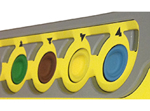
The TCA27 system consists of the installation of a light marker composed of 4 diodes of 4 different colours (red, yellow, blue and green) at a visible place and in the immediate surroundings of the application (travelling crane, crane or other).
This marker is controlled by the radio remote control on the same frequency and at the same address as for the other functions of the latter.
When the radio remote control starts up, the marker generates a colour code consisting of 2 colours; this code is random i.e. it will be different at each start-up .
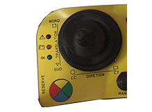
On the transmitter, 4 standard function keys are however given the colours red, yellow, blue and green. The operator therefore confirms the colour seen on the marker successively by pressing the corresponding key on the transmitter, and the confirmation operation of two random colours can take 5 seconds at most.
The random 2-colour code is quite sufficient for the majority of applications, but JMei can also configure the system to confirm a code of 3 colours or four if the need arises.
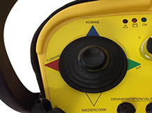
This system enables simultaneous control of two pieces of machinery (for example: travelling cranes) by a single transmitter. This allows the transport of long loads completely safely. With the "bi-directional" option, the system also ensures the management of travel limits, thus making the coupling very safe.
"Sole" operation
Either the "master" bridge is controlled by the "master" transmitter. Or the "slave" bridge is controlled by the "slave" transmitter. In this operating mode, the bridges are independent and are working on two separate frequencies.
"Tandem" operation
Either the "slave" transmitter is switched off. Or the "master" transmitter is started with "Tandem" mode activated (this mode is activated by a simple combination of buttons when the transmitter starts up, in order to avoid any unintentional activation).
In this operating mode, the two bridges are controlled by the "master" transmitter.
The master transmitter is fitted with a 1, 1+2 or 2 selector switch which chooses which bridge is to be controlled: the "master" (1), the "slave" (2) or both simultaneously (1+2).
The working frequency is thus unique for the two bridges and it is that of the "master".
Activation of the slave bridge by the two transmitters simultaneously is impossible.
When a bridge is controlled by the "master" transmitter but is not selected by the 1.1 + 2.2 selector switch, only the general contact switch remains engaged. The "horn" command remains active.
Various "handling" options of the "slave" bridge are possible:
The "Tandem" system presented here can be done with 2, 3 or 4 machines simultaneously.
In this case, the bridges are active side-by-side (contiguous bridges) or all together.
The system can be advantageously supplemented by the "bi-directional" option which allows a dialogue between receivers (and possibly between transmitters). In this case, the travel limits of the various bridges can be connected to the respective receivers and transmitted to the other bridge. In "Tandem" mode with the two bridges active at the same time (selector switch at 1 +2), the travel limits of the second bridge act on the first and vice versa. This means, for example, that the translatory movement of BOTH bridges can be stopped when one of the bridges arrives at the travel limit. This system also allows joint management of load limiters. With this option, both bridges are coupled "logically" to form a single bridge in complete safety.
